In the world of manufacturing, where surface quality is critical, fast and accurate defect detection is invaluable. One of the most effective methods is laser line scanning. But how does it actually work? In this post we'll look at how to direct the laser and how to observe it in order to detect even the smallest deformations. We'll then explain what those deformations mean and what information the height of the laser line deflection carries.
How to position the camera and laser to effectively detect surface defects?
Imagine shining a laser line onto an irregular surface while standing right behind it, observing it at the same angle as the light strikes. What would you see? Probably a perfectly straight line, as if the surface were flawlessly smooth.
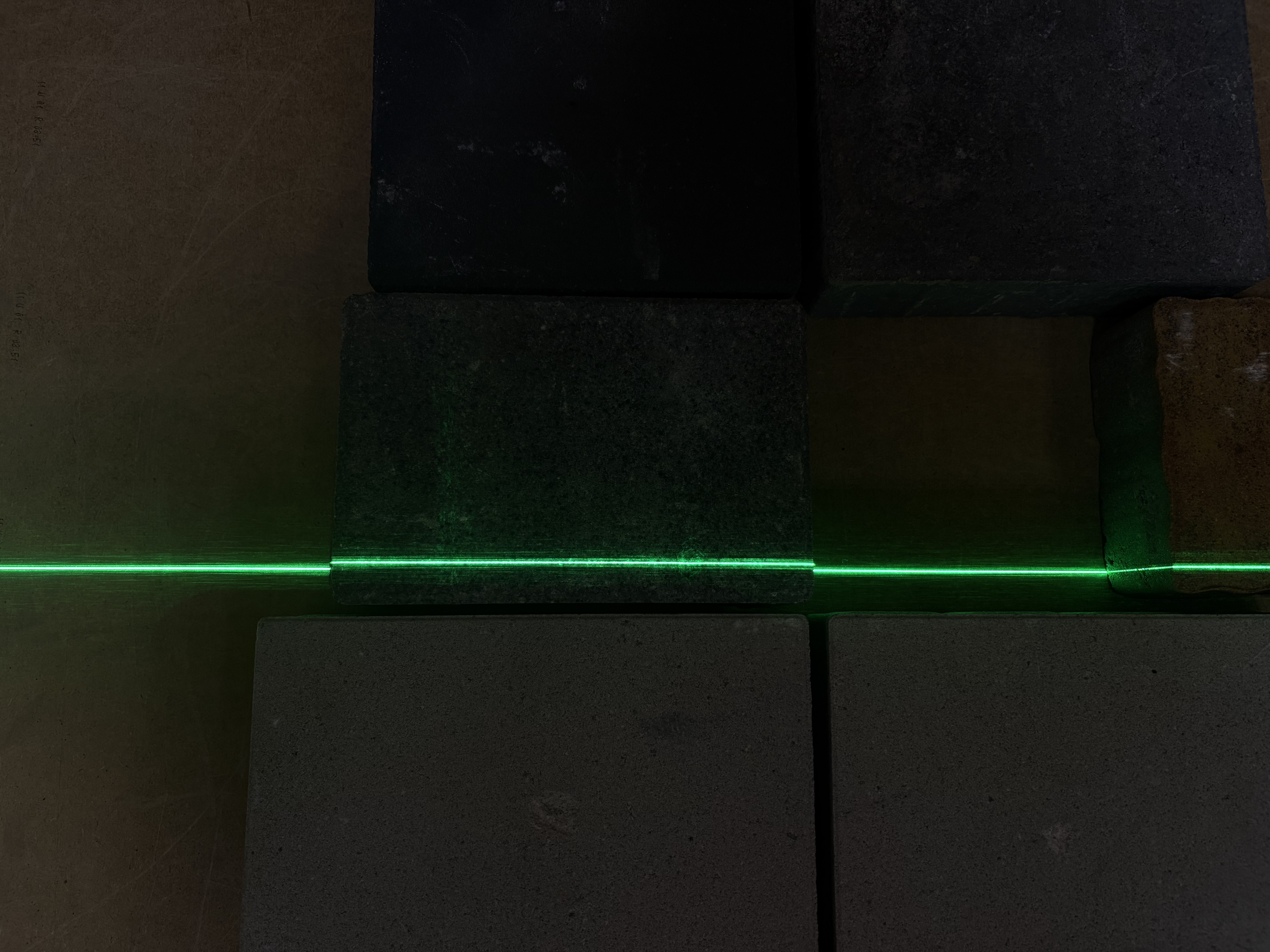
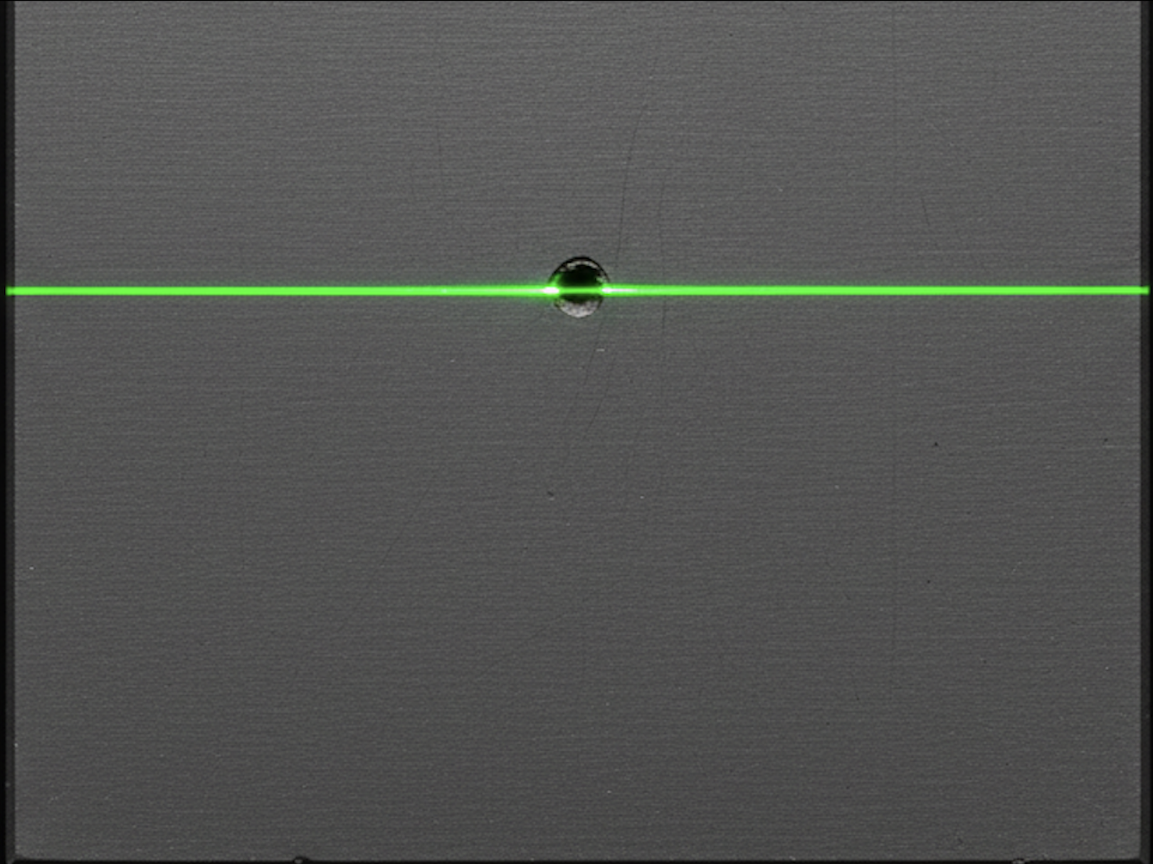
Photo 1 — laser line observed at the same angle as its angle of incidence
Photo 1 shows exactly this situation: the laser line is observed at the same angle at which it strikes the surface. The photo was taken with a low exposure so the background is dark, allowing better observation of the laser itself. In automated analysis, exposure is often set so low that only the laser is visible in the camera images.
To observe real deflections of the laser line on the irregular shapes it illuminates, we must change the observation position. We need to create an angle between the observer (camera) and the light source (laser). There are three basic component configurations:
- Laser strikes the surface at an angle, camera observes perpendicularly. The most intuitive approach, though it has a drawback we'll discuss in future posts.
- Laser strikes the surface perpendicularly, camera observes at an angle. A less intuitive solution, but often optimal — this is the option we chose for our advanced systems (more on this in future articles).
- Both components (laser and camera) are tilted relative to each other. This approach has its advantages, but we use it less frequently at this time.
What does laser line deflection on the inspected product mean?
The effect of laser line displacement in the configuration where the laser shines perpendicularly and the observer (camera lens) observes at an angle is key to defect detection. Look at Photo 2:
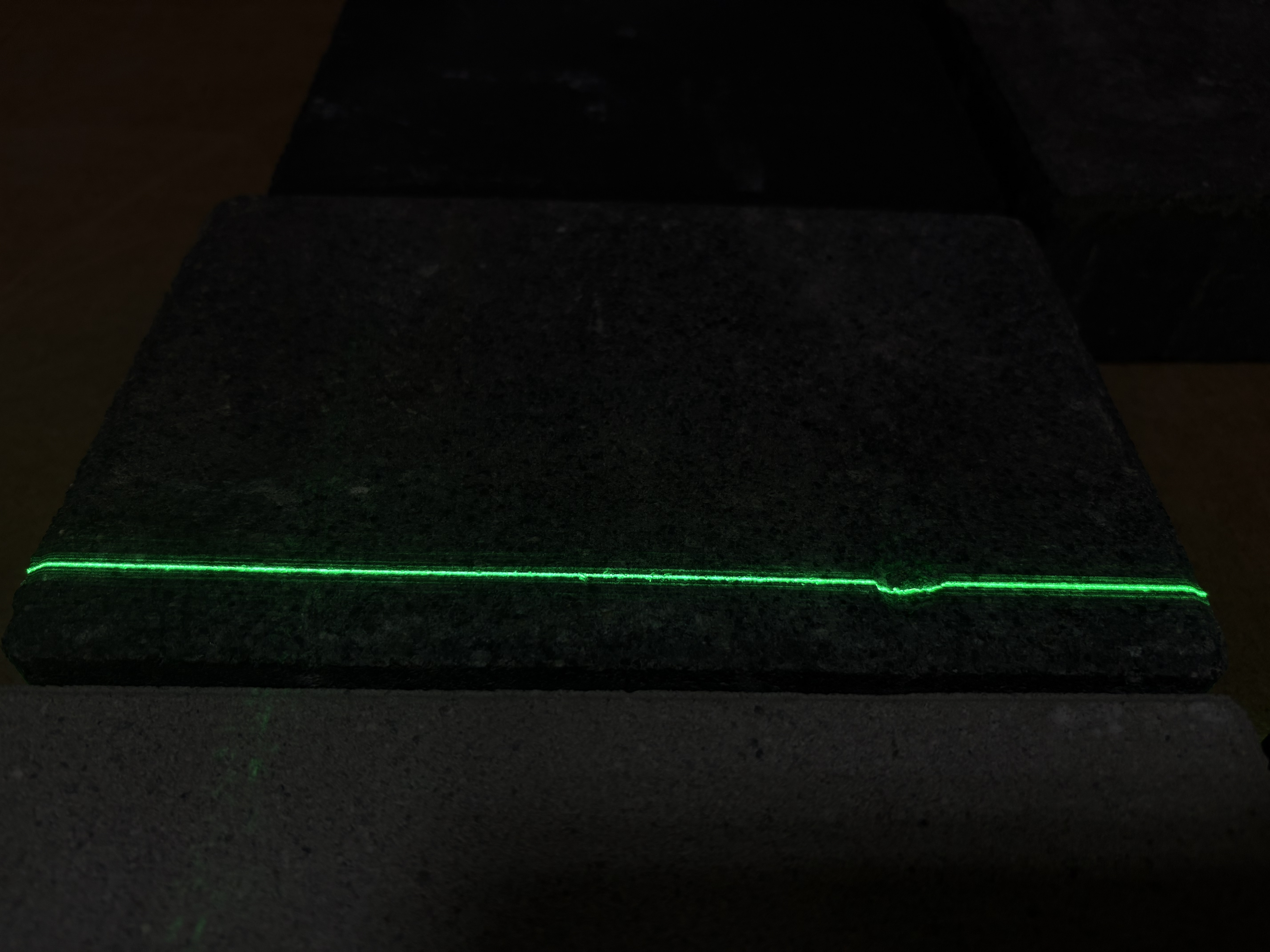
Photo 2 — laser line observed at a 45-degree angle
On the right side of the paving brick, a clear downward deflection of the laser line is visible (relative to the rest of the line). What does this mean? It means that there is a depression at that point — a potential hole or defect. Automated detection of such anomalies allows for lightning-fast identification of quality defects in the production process.
How to measure defect depth from laser line deflection?
Now that we know how to position the components to observe laser line bending on irregular surfaces, it's time to answer the question: what do these bends mean, and does their height carry any information?
As seen in Photo 2, the distortion of the laser line is directly caused by defects on the product. Therefore, identifying the distortion alone allows identification of the defect.
Moreover, the height of the laser line deflection when shining on a defect tells us about the depth of that defect. To measure defect depth, we need to know the angle between the components (laser and camera). Having this information along with the deflection height, we can calculate defect depth based on simple trigonometry.
The simplest angle for calculations is 45 degrees, because we then use the relationship of a right triangle with angles 45°, 45° and 90°. In this configuration, the height of the laser deflection equals the depth of the defect.
That covers the basics of laser line scanning. We hope this post has shown you how a simple change of perspective and the appropriate use of trigonometry can transform an ordinary line of light into a powerful quality control tool!