In computer vision systems, and particularly in production-line quality control, one brutal rule applies: Garbage In, Garbage Out (GIGO). You may have the most sophisticated AI model, but if you feed it weak, noisy or distorted data, the results will be unpredictable at best and costly at worst.
The camera is the eye of your system. In line scanning, where the product moves at high speed, choosing a camera is not a routine item on a shopping list. It is a fundamental design decision that directly defines the upper limit of accuracy and reliability for the entire system. A wrong decision at this stage is nearly impossible to compensate for in software.
In a previous post we defined a general list of camera parameters. Today we'll analyze the most important ones in the context of flat surface scanning, focusing on the technical trade-offs you will face when making this choice.
Sensor type and size
The first and most important decision about the sensor is the shutter type. There are two basic groups: rolling shutter and global shutter.
For systems that scan objects in motion, this choice is absolutely critical.
- Rolling Shutter: Reads the image line by line, from top to bottom. If the object moves faster than the full sensor readout time, the resulting image will be distorted (the "jello effect").
- Global Shutter: Exposes and reads all pixels simultaneously. It freezes motion, delivering a geometrically correct image.
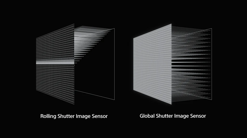
Comparison of sensor readout methods by shutter type.
The difference becomes dramatically visible when recording objects in motion. A rolling shutter sensor introduces artifacts that make precise measurement impossible and significantly complicate defect classification.
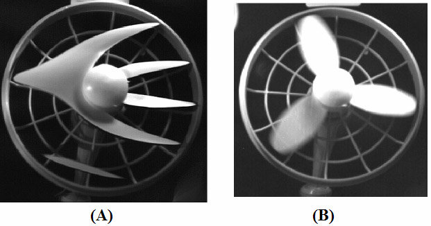
Comparison of a moving object by sensor type: A) rolling shutter (visible distortion), B) global shutter.
The conclusion is simple:
Rule #1: Wherever we record objects in motion (e.g. a product on a production line), using a sensor with a global shutter is absolutely essential to ensure the image passed to analysis is a faithful representation of reality.
The second key parameter is the sensor's physical size (e.g. 1/2", 2/3", 1"). A larger sensor — and typically larger pixels — means better signal-to-noise ratio (SNR) and higher sensitivity. At short exposure times dictated by line speed, the ability to collect as much light as possible is critical for obtaining a clean image.
Of course, a larger sensor means higher cost (both for the camera and the required optics). In our experience, for demanding production applications, sensors of 1 inch and larger offer noticeably better image quality and are worth considering as a starting point.
Resolution
This parameter directly translates to the level of detail. It must be matched to the size of the smallest defect (or feature) the system needs to reliably detect.
In engineering practice we apply a proven rule:
Rule #2: The smallest element of interest in the image should be represented by at least 3 to 5 pixels.
For example: if the working scan width is 1200 mm and the smallest defect we want to detect is 1 mm, our camera should have a horizontal resolution in the range of 3600 px (1200 / 1 × 3) to 6000 px (1200 / 1 × 5).
Higher resolution allows lower mean absolute error (MAE) and better detail reproduction, but comes with a trade-off: more data to process. This means higher demands on the computing unit and potentially slower system operation. "More" is not always "better" — the key is a balance between precision and computational efficiency.
Camera speed (FPS) vs. line speed
The frame capture rate (frames per second, FPS) must be synchronized with the production line. The critical parameter is the maximum linear speed of the product.
Lines often have variable speeds, so the vision system must be designed for the fastest possible operating scenario.
A key technique in line scanning is Region of Interest (ROI). Camera specifications give the maximum FPS when reading the entire sensor. However, for scanning a flat surface we don't need the full image height (e.g. 3000×3000 px). We can set the camera to read only a narrow window, e.g. 3000×400 px.
This significantly reduces the amount of data read from the sensor, which allows drastically increasing the effective frame rate, often several times over. This is standard optimization in this class of applications.
Many manufacturers (such as Basler) provide calculators to precisely calculate the achievable FPS for specific ROI settings.
Color or monochrome camera?
The choice is simpler than it seems. The default preferred choice in industrial applications should always be a monochrome (mono) camera.
Why?
- Smaller data volume: A mono image (8-bit) generates 3× less data than a color image (RGB, 24-bit). This directly translates to lower computational load and less demand on interface bandwidth.
- Higher sensitivity and sharpness: Color sensors use a Bayer filter where each pixel "sees" only one color (R, G or B). The values of the other two channels are interpolated (demosaicing), which slightly blurs the image. A mono pixel captures the full spectrum of light, giving it natively higher sensitivity and better detail sharpness — critical at short exposures.
Choose a color camera only when color is the key feature distinguishing the defect (e.g. print color inspection, detecting chemical discoloration).
Communication interface
In production environments the interface is not just a matter of bandwidth, but above all reliability and resistance to interference.
- USB: Simple to implement, popular in edge AI units (e.g. NVIDIA Jetson). Unfortunately, standard USB cables are susceptible to electromagnetic interference (EMI), especially at lengths > 3m. Nearby variable-frequency drives or motors can cause packet loss in camera communication.
- Ethernet: A considerably more robust choice; it is the industrial standard. Allows the use of long (up to 100 m), shielded cables. A key advantage is PoE (Power over Ethernet), which allows powering the camera and transmitting data over one cable, dramatically simplifying installation.
If the computing unit has only one Ethernet port (occupied e.g. by the factory network), it is worth adding a dedicated network card just for the camera rather than risking USB connection instability.
Built-in camera features
Modern industrial cameras are small computers. It's worth checking what functions they perform "on board" before the image reaches the computer.
- ROI (Region of Interest): As mentioned, key for increasing FPS.
- Binning: Merging adjacent pixels (e.g. 2×2) into one "super-pixel." This reduces resolution but radically increases light sensitivity (SNR) and readout speed. Useful in very low-light conditions.
- Trigger control: The camera's ability to be precisely triggered by an external signal (e.g. a photoelectric sensor detecting the start of a product) and to control lighting (e.g. a strobe lamp). Essential for synchronization with the line.
- Frame compression: If dealing with a large volume of data streamed to the computing unit, consider lossless frame compression in the camera itself. This offloads communication interfaces (e.g. Ethernet), and decompression happens before image analysis. This is especially significant when using multiple cameras in the system.
These features cannot be added programmatically after purchase. Knowing the problem and defining these requirements before selecting hardware is key to project success.