In the last three posts we went through the selection of the key components of a vision system for flat surface line scanning: camera, lens and line laser. Now it's time to assemble them into a working whole — that is, to build a station where these elements can be genuinely tested.
Line scanning requires that the inspected product passes beneath the measurement components — ideally at a constant speed, without stopping (there are also solutions allowing a stop mid-scan, but that's a separate topic). The test station must therefore simulate a production line. In practice this comes down to two elements: a drive system and a support structure for the measurement components.
Drive system — simulating the production line
The first element that needs to be worked on is the drive system simulating the production line. On it we place a pallet, and on the pallet — the products. In our case the products are paving bricks, sourced for research from local manufacturers.
On board we have Michał, who is responsible for automation and construction. The sketch of the system was done in a few minutes and it was immediately clear which direction we were heading.
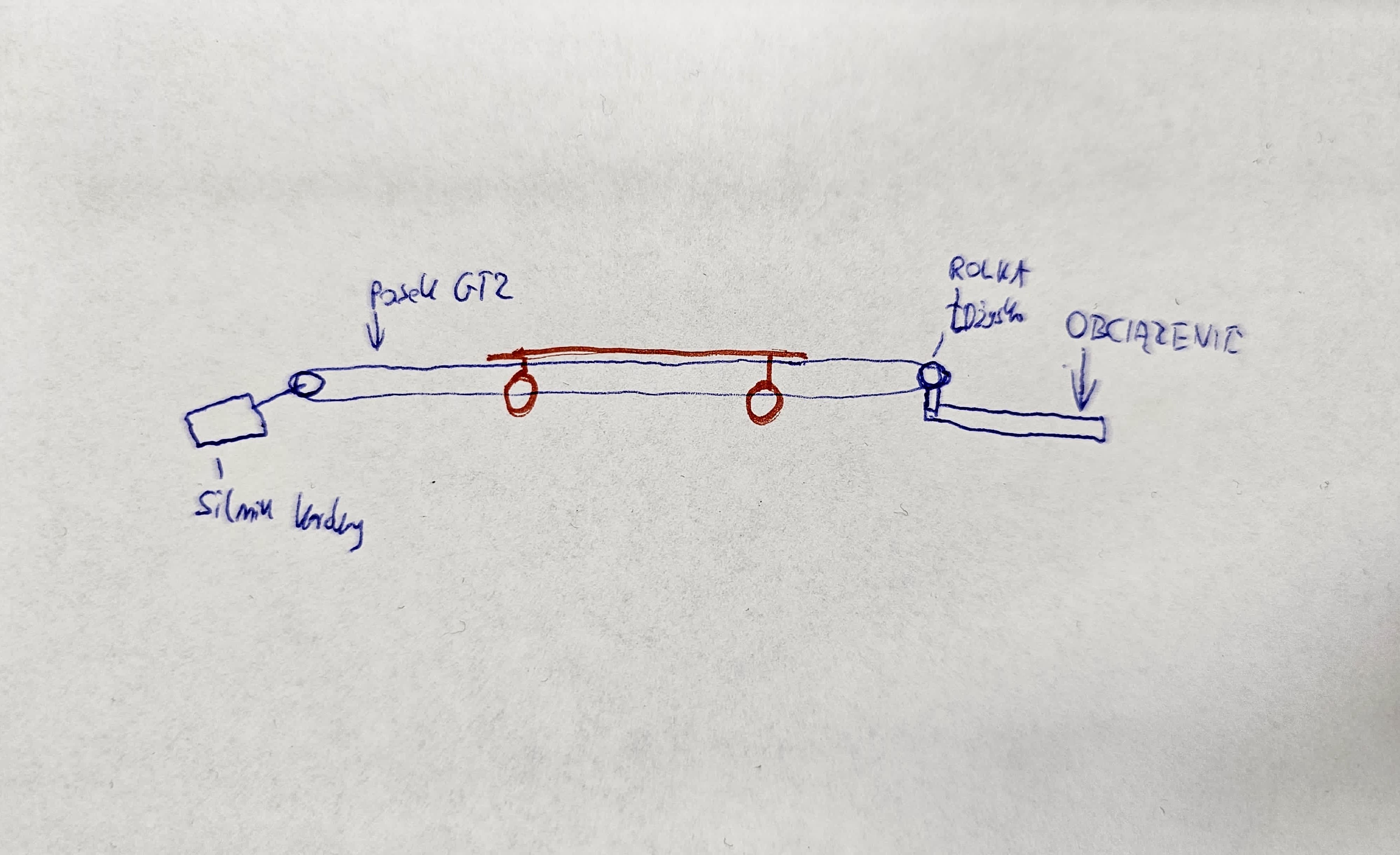
Photo 1: Drive system sketch
The operating principle is simple. The base frame consists of 20×20 aluminum profiles. At one end a stepper motor is mounted, at the other — a GT2 belt tensioner. Rollers are placed on the profiles, and further profiles responsible for pallet load-bearing are attached to them. These profiles on rollers are coupled with the GT2 belt, so the motor — via the belt — sets the pallet in motion. The assembled drive system is visible in Photo 2.
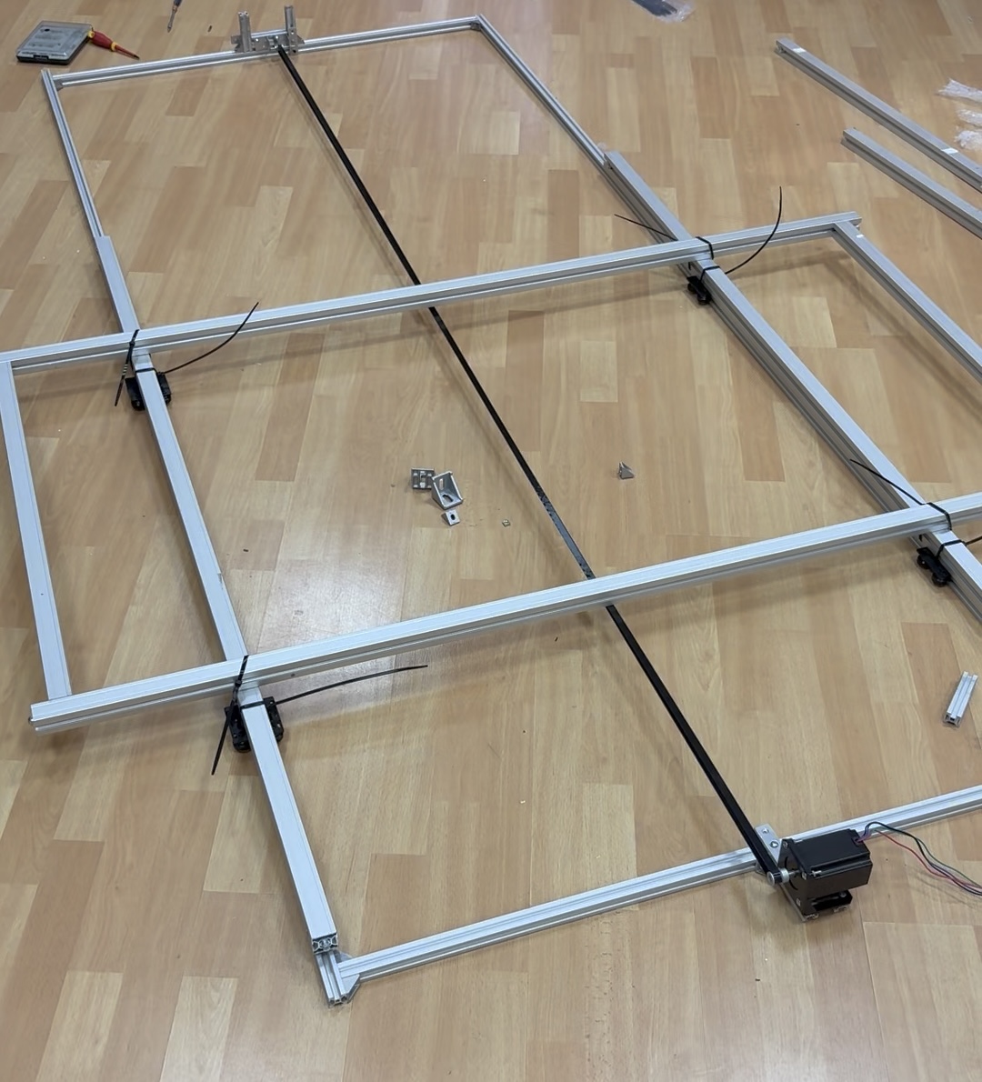
Photo 2: Assembled drive system
Support structure for the camera and line laser
Having the drive system, we need a structure to mount the previously selected components — the camera with lens and line laser. Again, Michał stepped in. Taking into account all the variables (laser lens opening angle, lens field of view, pallet width, possible product heights), he prepared a CAD design and sent it to a trusted profile supplier.
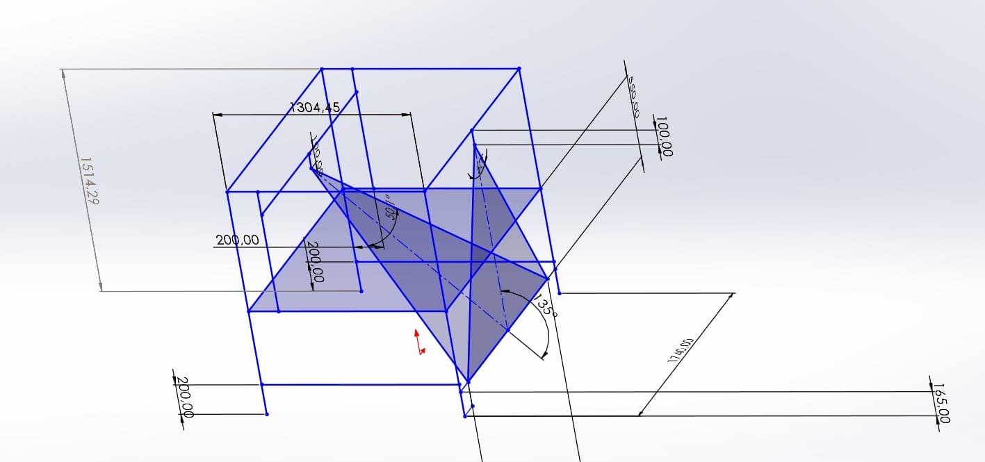
Photo 3: CAD design of the test station structure
Assembled test station and control automation
After delivery of the profiles we assembled everything. We have the structure with measurement components, underneath it the drive system, and next to it the automation controlling the system: speed, travel distance, acceleration, deceleration. The last two parameters matter because the pallet carries significant weight — with paving bricks you need to account for that.
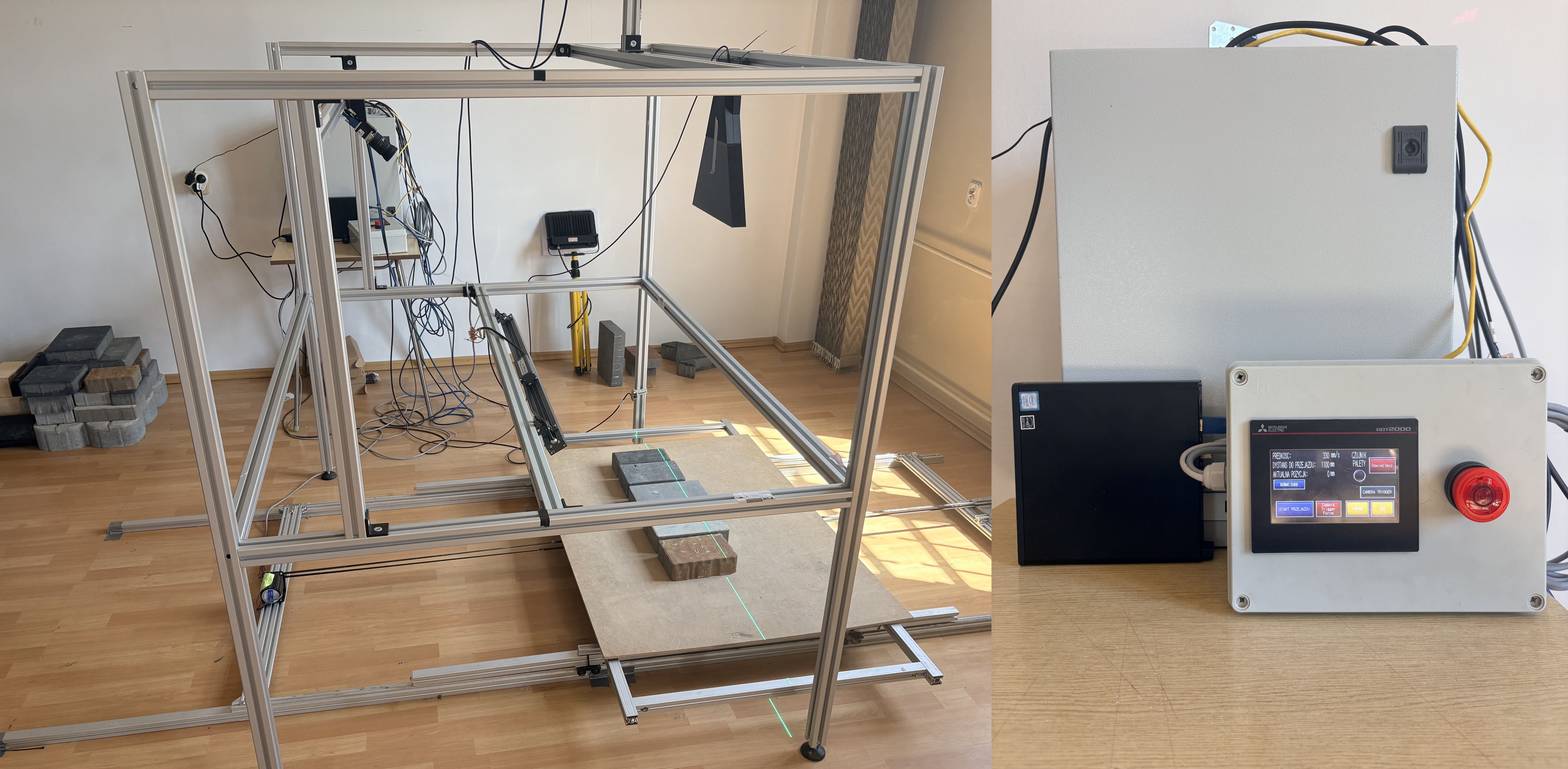
Photo 4: Complete laboratory — structure with measurement components, drive system and control automation
Why build your own test station?
Having such a station is invaluable. Above all, it allows us to prepare and test algorithms before production deployment — in any configuration, with any product arrangement, without the pressure of a client's production line.
However, it does not replace one thing: a pilot installation at a prospective client's site. In the next post I'll show why such a pilot is a real game changer — and what cannot be detected in a laboratory, no matter how well-equipped it is.